
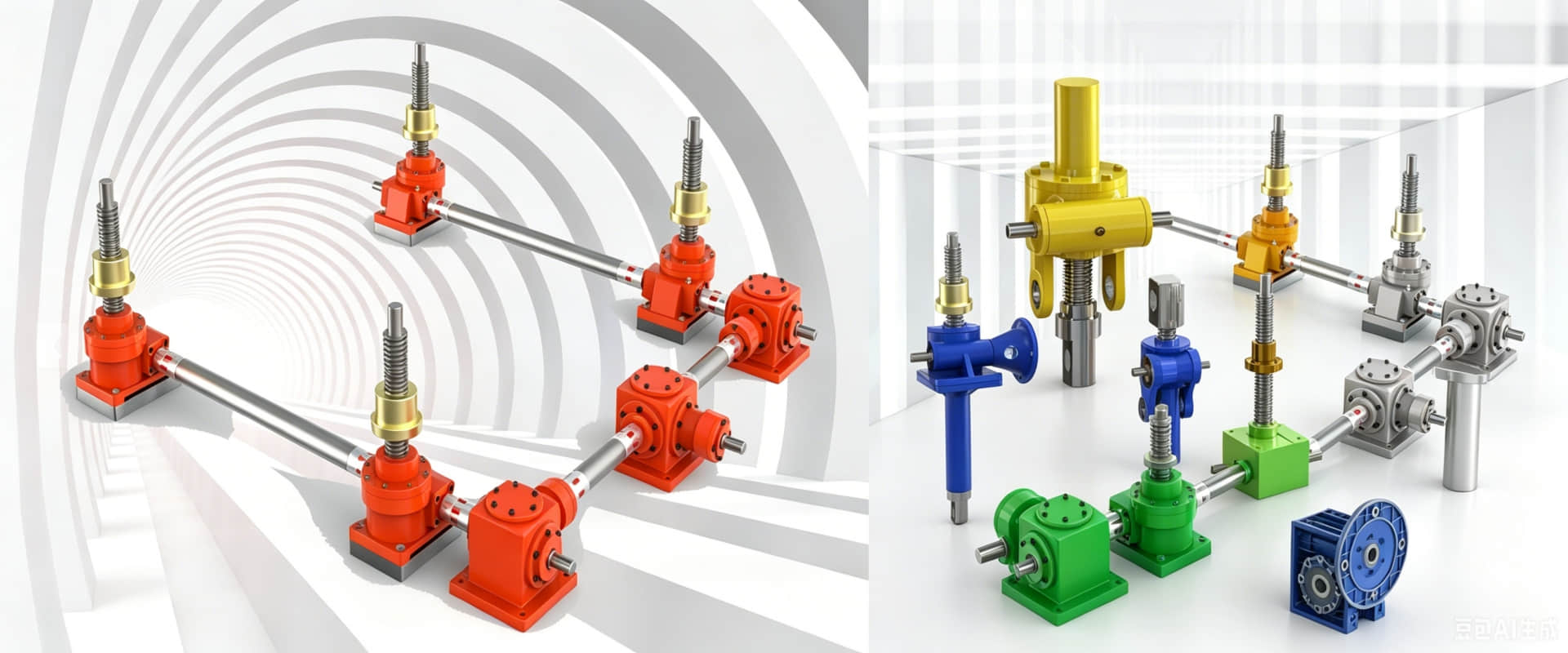
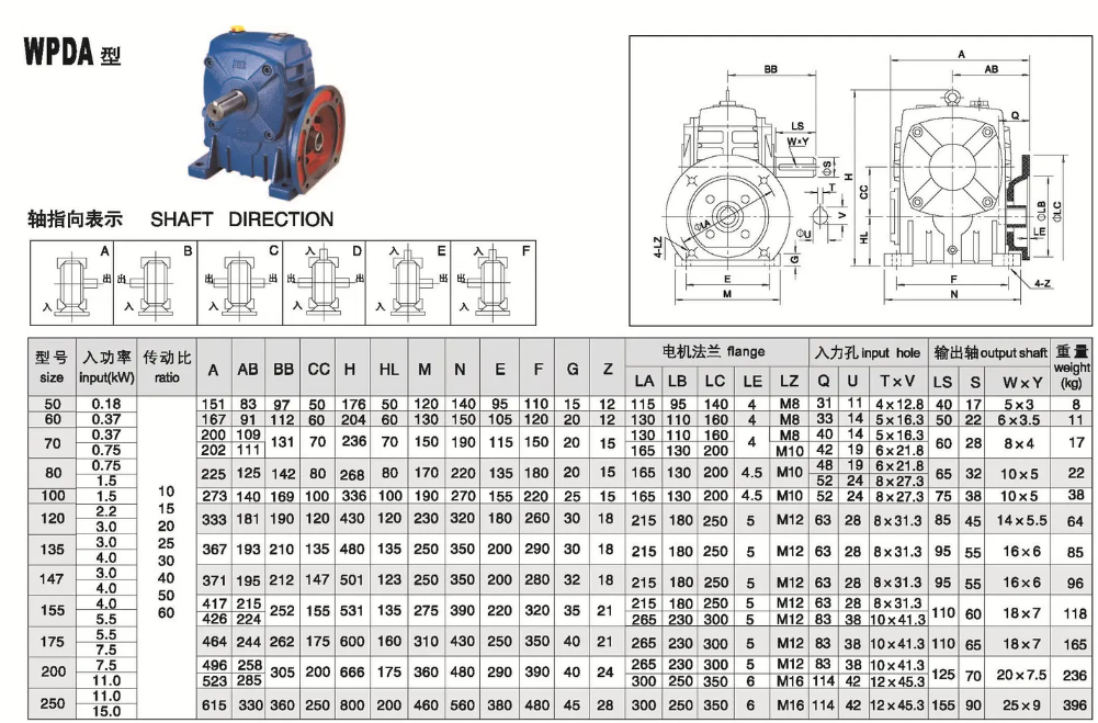
WPDA Series Cast Iron Worm Gear Reducer – Dimensions & Mounting Drawings (Lower Input Flange)
WPDA Series Worm Gear Reducer – Dimensions & Mounting Drawings
The WPDA series worm gear reducer features a lower input flange configuration. The motor mounts directly onto the input flange positioned below the output shaft, enabling direct coupling without additional couplings or belt drives.
Key Features
●Cast iron housing – heavy-duty construction
●Lower input flange – direct motor mounting (IEC standard flange)
●45# hardened steel worm + tin bronze worm wheel
●Self-locking capability
●Ratios: 10:1 – 60:1 (single stage)
●Space-saving – eliminates coupling and reduces footprint
Standard Sizes Available
WPDA series covers sizes 50, 60, 70, 80, 100, 120, 135, 155, 175, 200, 250
Mounting Dimensions (Typical Drawing References)
| Dimension | Description | Size 100 (Reference) |
|---|---|---|
| A | Center distance | 100 mm |
| Flange Type | IEC B5 or B14 | Refer to drawing |
| Input Flange Position | Lower (below output) | — |
| Output Shaft | Diameter × Keyway | Refer to drawing |
When to Choose WPDA?
Choose WPDA when you need a compact, direct-drive solution where the motor mounts directly to the gearbox input flange without additional coupling.
Related article: Detailed parameters of WPDA series reducers