
ZDY reducer: 9 assembly forms and external dimension drawings
ZDY Gear Reducer: Assembly Forms (I to IX) and Outline Dimension Guide
The assembly form of the ZDY series gearbox strictly follows the JB/T8853-2001 national standard, which includes 9 standard assembly forms. The core difference is the axis extension arrangement direction of the input shaft and output shaft, which adapts to the equipment layout requirements of different sites.
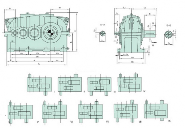
Type I: The input shaft extends unilaterally on the left side of the box, and the output shaft extends unilaterally on the right side of the box. It is the most commonly used basic horizontal layout, suitable for conventional scenarios where the motor is on the left and the load is on the right.
Type II: The input shaft extends unilaterally on the right side of the box, and the output shaft extends unilaterally on the left side of the box, mirror symmetric with Type I, suitable for installation requirements in reverse space on site.
Type III: The input shaft extends on both sides, and the output shaft extends on one side on the right side of the box. It can be connected to two power sources at the same time, or accessories such as speed encoders and brakes can be installed on the input side.
Type IV: The input shaft extends on both sides, and the output shaft extends on one side on the left side of the box, which is a mirror version of Type III.
Type V: The output shaft extends on both sides, and the input shaft extends on one side on the left side of the box, which can simultaneously transmit torque to the load devices on both sides. It is commonly used in dual drive conveyor lines.
Type VI: The output shaft extends on both sides, and the input shaft extends on one side on the right side of the box, which is a mirror version of Type V.
Type VII: The input shaft extends on both sides, the output shaft extends on both sides, and all four shaft ends extend outward, enabling a complex transmission layout with multiple power inputs and multiple load outputs.
Type VIII: Specially customized shaft end misalignment arrangement, suitable for non-standard racks with spatial interference on site.
Type IX: A special assembly form with auxiliary installation flanges, compatible with some vertical transition installation scenarios.
Please send your required power, output speed, torque and installation space drawing, our engineer will recommend the suitable gear model for you for free. CAD 2D / 3D STEP files available upon request.