
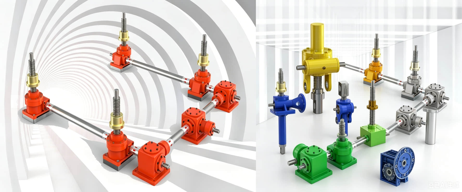
WPX Series Cast Iron Worm Gear Reducer – Dimensions & Mounting Drawings (Vertical Downward Output)
WPX Series Worm Gear Reducer – Dimensions & Mounting Drawings
The WPX series worm gear reducer features a vertical downward output shaft configuration. The output shaft extends vertically downward, making it the ideal choice for applications where the driven equipment is positioned below the reducer.
Key Features
Cast iron housing – robust for vertical overhead mounting
Vertical downward output – output shaft points down
45# hardened steel worm + tin bronze worm wheel
Self-locking capability – safety for suspended loads
Ratios: 10:1 – 60:1 (single stage)
Standard Sizes Available
WPX series covers sizes 40, 50, 60, 70, 80, 100, 120, 135, 147, 155, 175, 200, 250
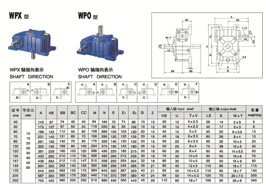
Mounting Dimensions (Typical Drawing References)
| Dimension | Description | Size 100 (Reference) |
|---|---|---|
| A | Center distance | 100 mm |
| AB | Base mounting hole spacing | Refer to drawing |
| H | Overall height | Refer to drawing |
| HL | Overall length | Refer to drawing |
| Output Shaft Orientation | Vertical downward | — |
| Input Shaft | Diameter × Keyway | Refer to drawing |
| Output Shaft | Diameter × Keyway | Refer to drawing |
Full dimension drawings available – contact us for PDF catalog.
When to Choose WPX?
Choose WPX when your gearbox is mounted overhead and the driven equipment (e.g., suspended conveyor, agitator from top) is positioned below.