
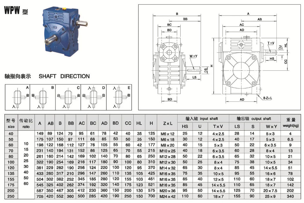
WPW series worm gear reducer size and installation diagram, size 40-250, shaft input type.
WPW Series Worm Gear Reducer – Dimensions & Mounting Drawings
The WPW series worm gear reducer features a universal housing design with multiple threaded mounting holes on all sides. Unlike standard foot-mounted types, the WPW series offers maximum installation flexibility – mount it horizontally, vertically, or at any angle
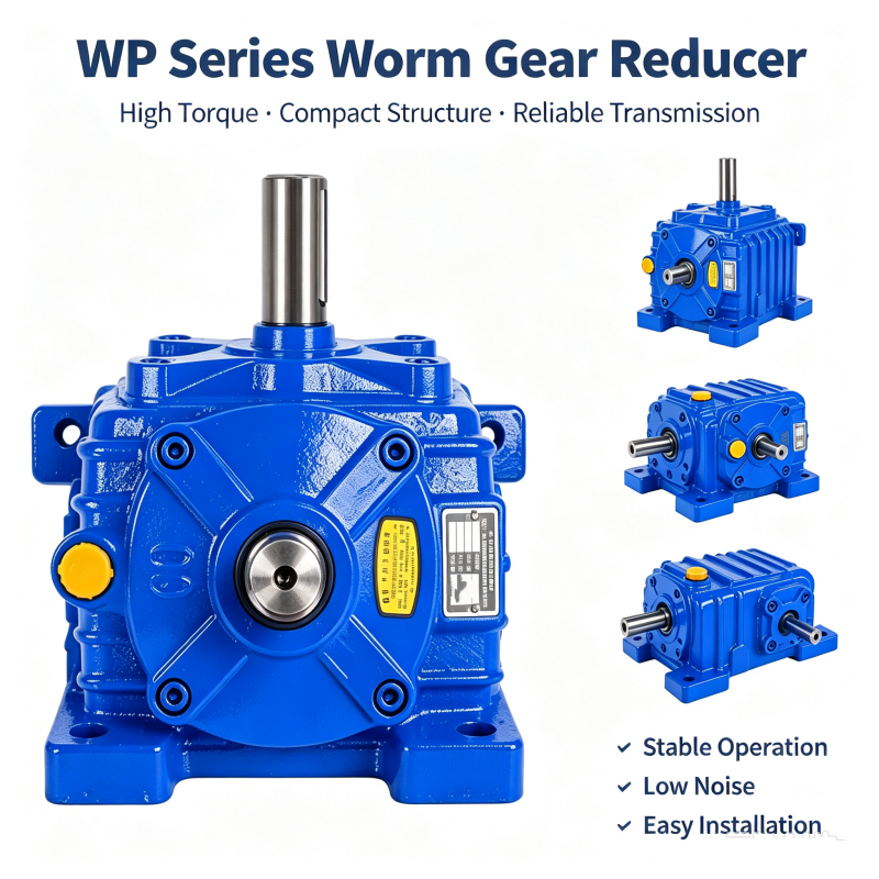
Main features of WP series cast iron worm gear box
●Cast iron casing - universal design with multi-faceted threaded holes
●No need for a base plate - directly fixed to the machine frame with bolts
●45 # hard steel worm gear+tin bronze worm gear
●self-locking capability
●Proportion: 10:1-60:1 (single-stage)
●Maximum flexibility - any installation direction
Sub-variants
| Model | Description |
| WPW | Standard universal housing |
| WPWA | Universal with lower input shaft |
| WPWS | Universal with upper input shaft |
| WPWO | Universal with vertical upward output |
| WPWV | Universal with vertical output |
| WPWT | Universal with special configuration |
Full dimension drawings available – contact us for PDF catalog.
When to Choose WPW?
Choose WPW when your application requires non-standard mounting orientations or when the gearbox needs to be bolted directly to a machine frame without a baseplate.
Related article: Advantages and materials of WP series cast iron turbine reducer