
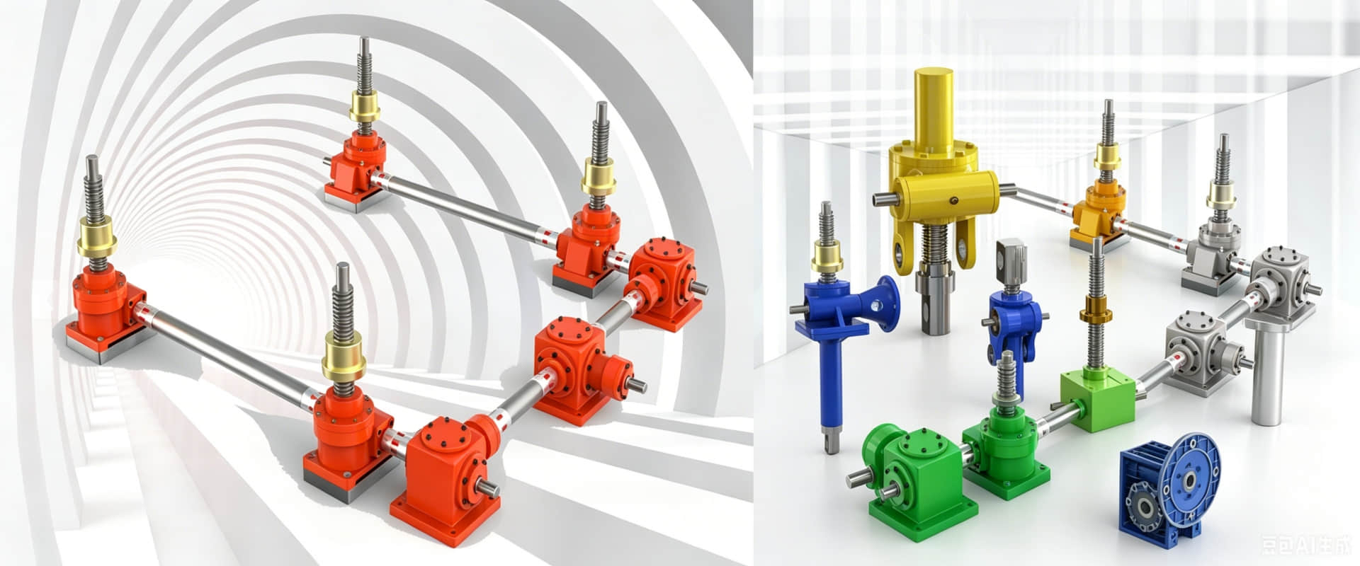
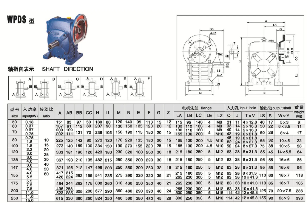
WPDS Series Cast Iron Worm Gear Reducer – Dimensions & Mounting Drawings (Upper Input Flange)
WPDS Series Worm Gear Reducer – Dimensions & Mounting Drawings
The WPDS series worm gear reducer features an upper input flange configuration. The motor mounts directly onto the input flange positioned above the output shaft, enabling direct coupling with the motor mounted on top
Key Features
Cast iron housing – durable and strong
Upper input flange – direct motor mounting from above
45# hardened steel worm + tin bronze worm wheel
Self-locking capability
Ratios: 10:1 – 60:1 (single stage)
Compact design – ideal for limited floor space
Standard Sizes Available
WPDS series covers sizes 50, 60, 70, 80, 100, 120, 135, 155, 175, 200, 250
Mounting Dimensions (Typical Drawing References)
| Dimension | Description | Size 100 (Reference) |
|---|---|---|
| A | Center distance | 100 mm |
| Flange Type | IEC B5 or B14 | Refer to drawing |
| Input Flange Position | Upper (above output) | — |
| Output Shaft | Diameter × Keyway | Refer to drawing |
Full dimension drawings available – contact us for PDF catalog.
When to Choose WPDS?
Choose WPDS when space is limited at the bottom of the gearbox and the motor needs to be mounted on top for accessibility or clearance.
Related article: Advantages, materials, and application scenarios of WP series cast iron turbine reducers.