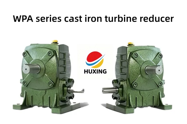
WPA Series Cast Iron Worm Gear Reducer – Dimensions & Mounting Drawings (Lower Input Shaft)
WPA Series Worm Gear Reducer – Dimensions & Mounting Drawings
The WPA series worm gear reducer features the worm shaft positioned below the output shaft (lower input shaft configuration). This foot-mounted, cast iron housing design is the most widely used configuration in the WP series, ideal for standard horizontal applications with ample floor space
Key Features
1.Cast iron housing – rugged, durable, excellent heat dissipation
2.Lower input shaft – standard configuration for horizontal mounting
3.45# hardened steel worm + tin bronze worm wheel – exceptional wear resistance
4.Self-locking capability – prevents back-driving for safety
5.Ratios: 10:1 – 60:1 (single stage)
Standard Sizes Available
WPA series covers sizes 40, 50, 60, 70, 80, 100, 120, 135, 147, 155, 175, 200, 250
Mounting Dimensions (Typical Drawing References)
| Dimension | Description | Size 100 (Reference) |
| A | Center distance | 100mm |
| AB | Base mounting hole spacing | Refer to drawing |
| H | Overall height | Refer to drawing |
| HL | Overall length | Refer to drawing |
| Input Shaft | Diameter × Keyway | Refer to drawing |
| Output Shaft | Diameter × Keyway | Refer to drawing |
Full dimension drawings available – contact us for PDF catalog.
WP series cast iron turbine reducer adaptation scenarios
Suitable for horizontal continuous transmission scenarios ranging from light to medium loads, such as small conveyors, mixers, textile machinery, packaging machinery, woodworking machinery, etc., especially suitable for long-term continuous operation and high lubrication reliability requirements.