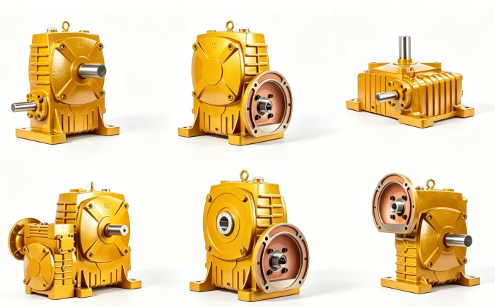
WP reducer power input power calculation (reference - single-stage 1500 r/min)
Output Torque by Frame Size (Reference – Single Stage)
| Frame Size | Output Torque Range (N·m) |
|---|
| 40 | 19 – 25 |
| 60 | 31 – 39 |
| 70 | 50 – 75 |
| 80 | 83 – 113 |
| 90 | 113 – 151 |
| 100 | 193 – 291 |
| 120 | 262 – 413 |
| 135 | 540 – 707 |
| 147 | 566 – 739 |
| 155 | 709 – 848 |
| 175 | 958 – 1221 |
| 200 | 1280 – 1782 |
| 250 |
Torque varies by ratio – lower ratios deliver higher torque
Key Materials & Construction
●Housing: High-strength cast iron (HT250)
●Worm Shaft: 45# high-quality steel, heat-treated
●Worm Wheel: Tin bronze casting
Input Speed Limit
Maximum worm shaft speed: 1,500 r/min – exceeding this limit accelerates wear and reduces service life.
Selection Quick Reference
When selecting a WP series reducer:
Determine required ratio –
i = Input Speed / Output SpeedCalculate load torque – ensure rated torque ≥ your requirement
Select frame size – based on torque capacity from specification table
Verify input power – motor power must not exceed reducer's thermal rating
Choose mounting configuration – WPA/WPS/WPO/WPX/WPDA/WPDS/WPW
Need help selecting the right model? Send us your motor power, required output speed, load torque, and mounting preference – our engineering team responds within 24 hours.