
Wiring diagram of micro governor variable speed gear motor
H1: Variable Speed Gear Motor Wiring Diagram with Speed Controller
H2: Motor to Speed Controller Connection
This variable speed gear motor uses 6 lead wires: Yellow, Blue, White, Red, Black, and Green. The US-52 speed controller has matching terminals. Connect the motor wires to the controller wires color-to-color (main line to main line). Ensure all terminals are tight and secure.
H2: 220V AC Power Connection
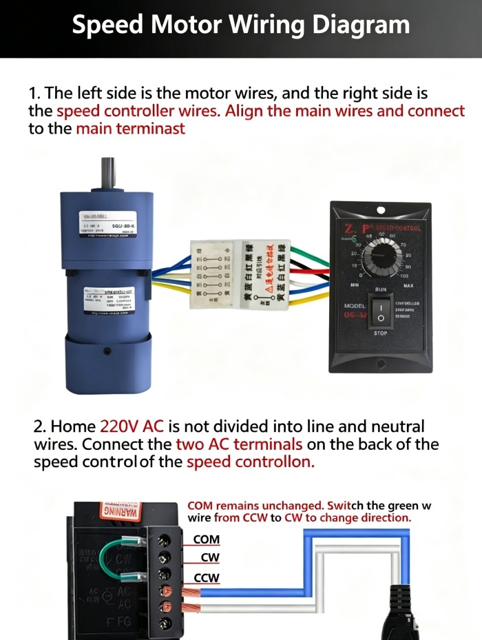
The US-52 controller operates on 220V AC household power. Connect the two AC wires to the AC N and AC L terminals on the back. For 220V AC, live and neutral are interchangeable. Connect the ground wire to the FG terminal if available.
H2: Forward and Reverse Rotation Switching
The controller has COM, CW, and CCW terminals. COM remains fixed.
Forward rotation: Connect the Green wire to CW.
Reverse rotation: Connect the Green wire to CCW.
⚠️ Always stop the motor before switching rotation direction.