Selection method of WP worm gear reducer
To select the appropriate WP worm gear reducer, follow these steps:
Step 1: Determine Load Torque & Speed Requirements
Start by calculating the torque and speed your driven equipment requires.
Torque formula:
T = 9550 × P / n
Where T = torque (N·m), P = power (kW), n = speed (r/min).
For load-driven calculations, determine the resistance torque from your equipment (e.g., conveyor belt tension, mixer resistance) and convert it to the required output torque at the reducer shaft.
Step 2: Calculate the Reduction Ratio
The reduction ratio is determined by:
i = n₁ / n₂
Where n₁ = motor input speed (typically 1450 r/min for 4-pole motors), n₂ = required output speed.
Select the standard ratio closest to your calculated value from the WP series available ratios: 10, 15, 20,
25, 30, 40, 50, 60 (single stage).
Step 3: Account for Efficiency & Apply Service Factor
Worm gear reducers typically have 60–90% efficiency – efficiency is lower at higher ratios.At 50:1 ratio, typical efficiency is 65–70%.
Theoretical output torque:
T₂₀ = T₁ × i × η
Where T₁ = motor torque, i = reduction ratio, η = efficiency.
Apply a service factor based on your duty cycle:
| Duty Condition | Service Factor (f) |
|---|---|
| Smooth, continuous operation | 1.2 |
| Moderate impact / shock loads | 1.3 |
| Heavy shock, frequent start-stop | 1.5 |
Selection torque:
T₂ = T₂₀ × f
Step 4: Select Mounting Configuration
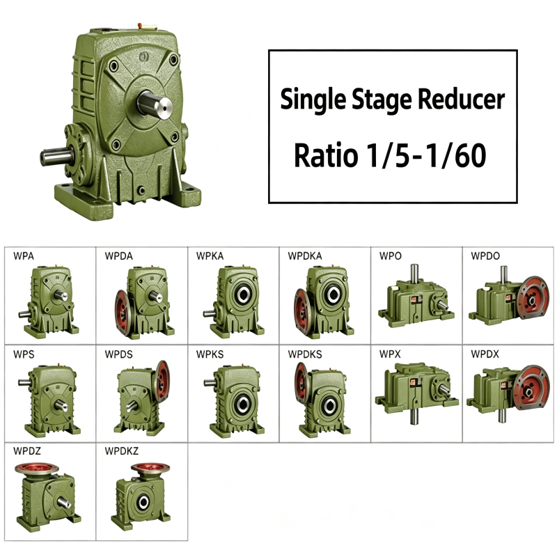
WP series offers four primary mounting configurations
| Model Code | Configuration | Worm Position |
|---|---|---|
| WPA | Horizontal (foot-mounted) | Worm underneath |
| WPO | Horizontal (foot-mounted) | Worm on top |
| WPDA | Vertical (foot-mounted) | Worm underneath |
| WPDO | Vertical (foot-mounted) | Worm on top |
Choose based on your available space, shaft orientation, and equipment layout