
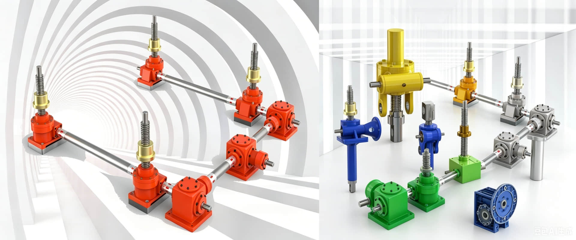
Installation and Maintenance of NMRV Series Reducer | Structural Diagram
This article provides a detailed breakdown of the core structure and standard installation process of the NMRV series worm gear reducer, helping you quickly grasp the key points of equipment maintenance and extend its service life.
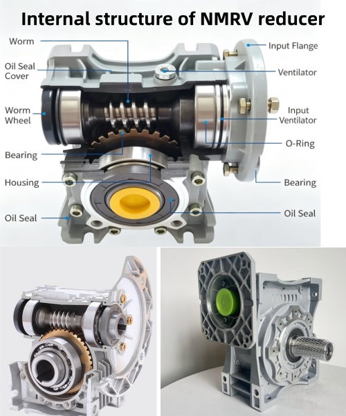
1、 Diagram of the Core Structure of NMRV Reducer
1. Transmission system
Worm: Made of 20Cr steel treated with carbonitriding, it has high surface hardness and good wear resistance.
Worm gear: Made of wear-resistant aluminum bronze (ZCuAl10Fe3), it meshes with the worm to achieve high speed ratio reduction.
Bearings: Deep groove ball bearings are used at the input end, and tapered roller bearings are used at the output end to support rotating components and withstand radial and axial loads.
2. NMRV gearbox housing and seal
Box body: Machine base number 025-090 is made of die cast aluminum alloy, and 110 and above are
made of cast iron material, balancing lightweight and high strength.
Sealing: The input/output shaft end adopts a skeleton oil seal (usually nitrile rubber) to prevent
lubricating oil leakage.
3. Gearbox installation interface
Input flange: Standard B5/B14 flange, can be directly connected to the motor.
Output shaft: Solid or hollow shaft with keyway design, convenient for connecting with load equipment.
Installation base: Reserve standard installation holes and support two methods of foot installation and flange installation.
2、 Standard installation process for reducers
1: Before installation, check and verify whether the reducer model, speed ratio, and installation dimensions match the motor and equipment. Clean all joint surfaces and remove rust proof oil and impurities.
2: Use a dial gauge to calibrate the coaxiality of the motor and gearbox input shaft for alignment and connection, with a deviation of ≤ 0.1mm. Priority should be given to using elastic couplings for connection, and direct hammering of the shaft end is strictly prohibited.
3: Fix and lubricate the installation bolts evenly in diagonal order. Adjust the oil injection amount according to the installation orientation (horizontal installation oil injection to the centerline of the oil window; vertical installation requires an increase of 10% oil injection).
4: Test run and inspect the no-load operation for 30 minutes, checking for any abnormal vibration, noise, and temperature rise. Gradually increase the load to the rated value and observe the operating status.