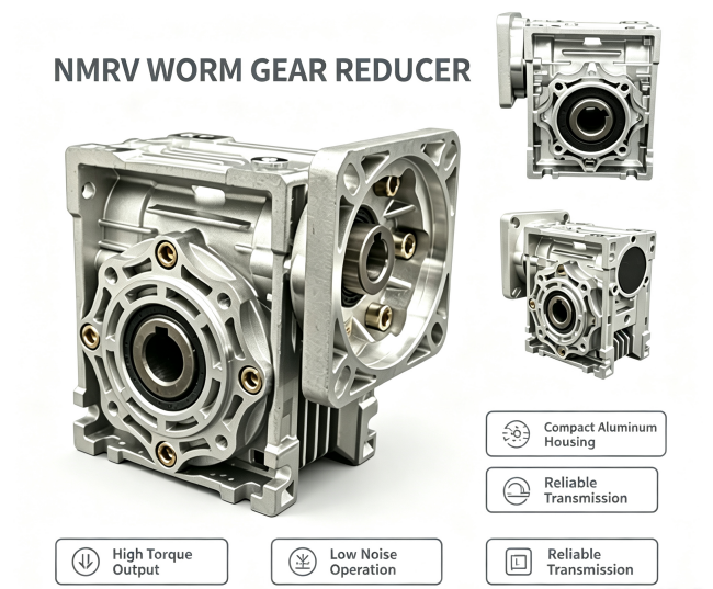
NMRV Worm Gear Reducer Frame Size Chart | Standard Installation Dimensions
1.standard NMRV reducer dimension table
| frame size | Flange diameter | Output shaft diameter | Standard keyway size |
| NMRV25 | 63mm | 11mm | 4×4mm |
| NMRV30 | 71mm | 14mm | 5×5mm |
| NMRV40 | 80mm | 18mm | 6×6mm |
| NMRV50 | 90mm | 22mm | 6×6mm |
| NMRV63 | 110mm | 25mm | 8×7mm |
| NMRV75 | 130mm | 28mm | 8×7mm |
| NMRV90 | 180mm | 32mm | 10×8mm |
| NMRV110 | 200mm | 38mm | 12×8mm |
| NMRV130 | 250mm | 45mm | 14×9mm |
| NMRV150 | 300mm | 50mm | 16×10mm |
2、 Key points for matching and selecting NMRV worm gear reducers
The motor flange needs to correspond exactly with the input flange size of the reducer, and customized flanges from different brands can be adapted to any brand of servo/asynchronous motor.
An adjustment allowance of at least 10mm should be reserved for the installation base. For scenarios with high vibration, it is recommended to pair it with a base with rubber shock absorbers.
When directly connected to a heavy-duty motor, an additional motor support device needs to be installed to prevent the shaft from being damaged by additional radial forces.