
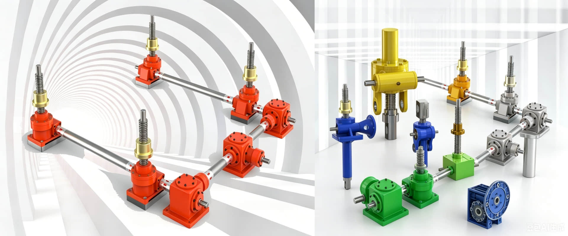
JWM Spiral Jack Load Diagram - Corresponding Measures
JWM Spiral Jack Load Diagram - Allowable Lateral Load, Buckling Stability, and External Guidance Requirements
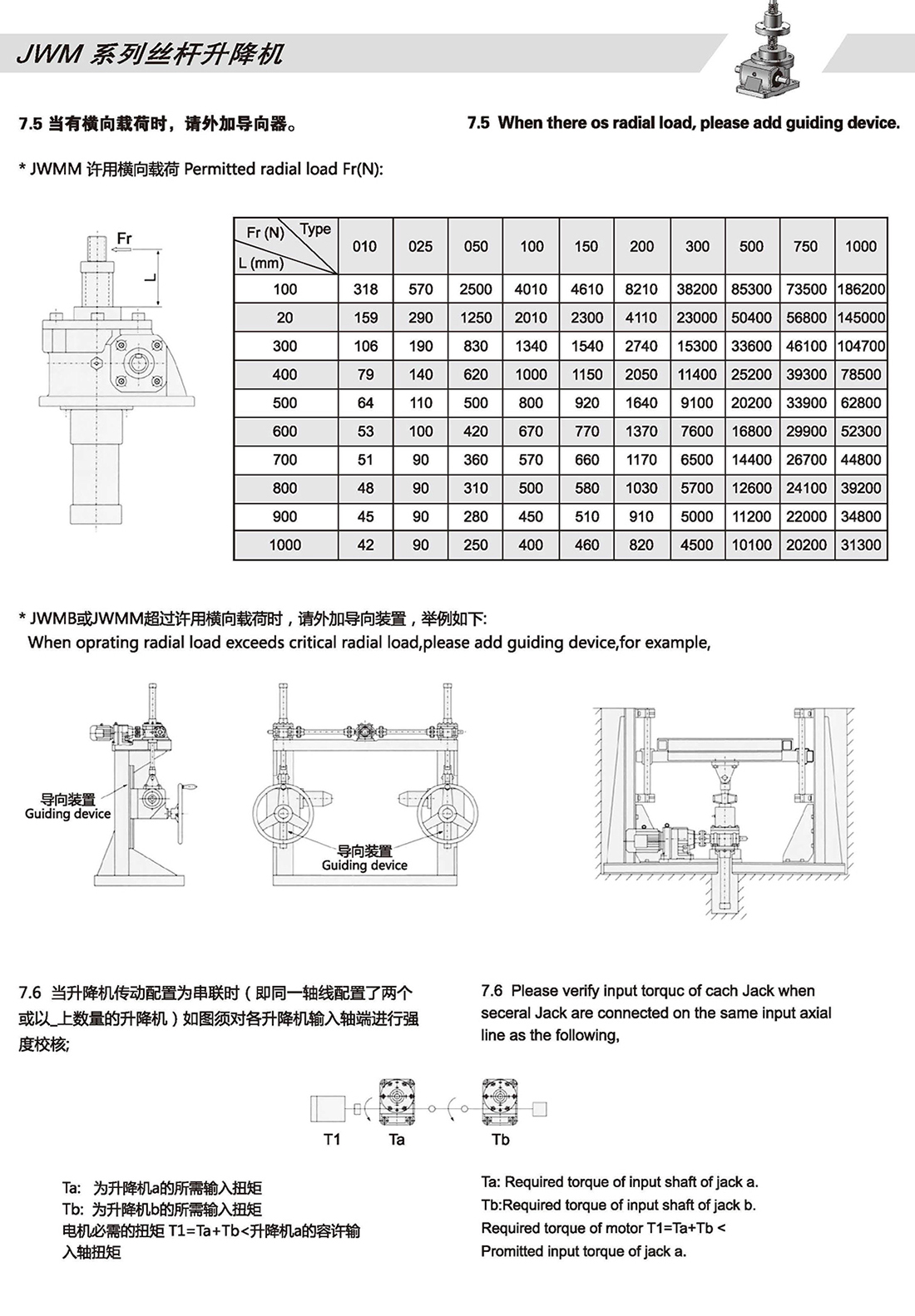
What This Chart Covers
| Section | What It Shows | Why It Matters |
| Allowable Side Load | Maximum lateral force Fr (N) vs. unsupported screw length L (mm) | Prevents screw bending and premature wear |
| Buckling Stability | Allowable buckling load vs. stroke distance (SF=4) | Prevents screw buckling under compression loads |
| External Guide | When and how to add linear guides | Protects the jack from side loads |
How to Read the Chart
For side load verification:
Find your stroke distance L (mm) on the horizontal axis
Find your JWM model on the chart
The curve shows the maximum allowable Fr (N) – stay below this line
If your side load exceeds the limit, external guides are required
Do you need dimension drawings and 3D models, product catalogs, or customized scale quotations? Please fill in the required model, power, and installation type, and our engineers will reply to you within 24 hours.