
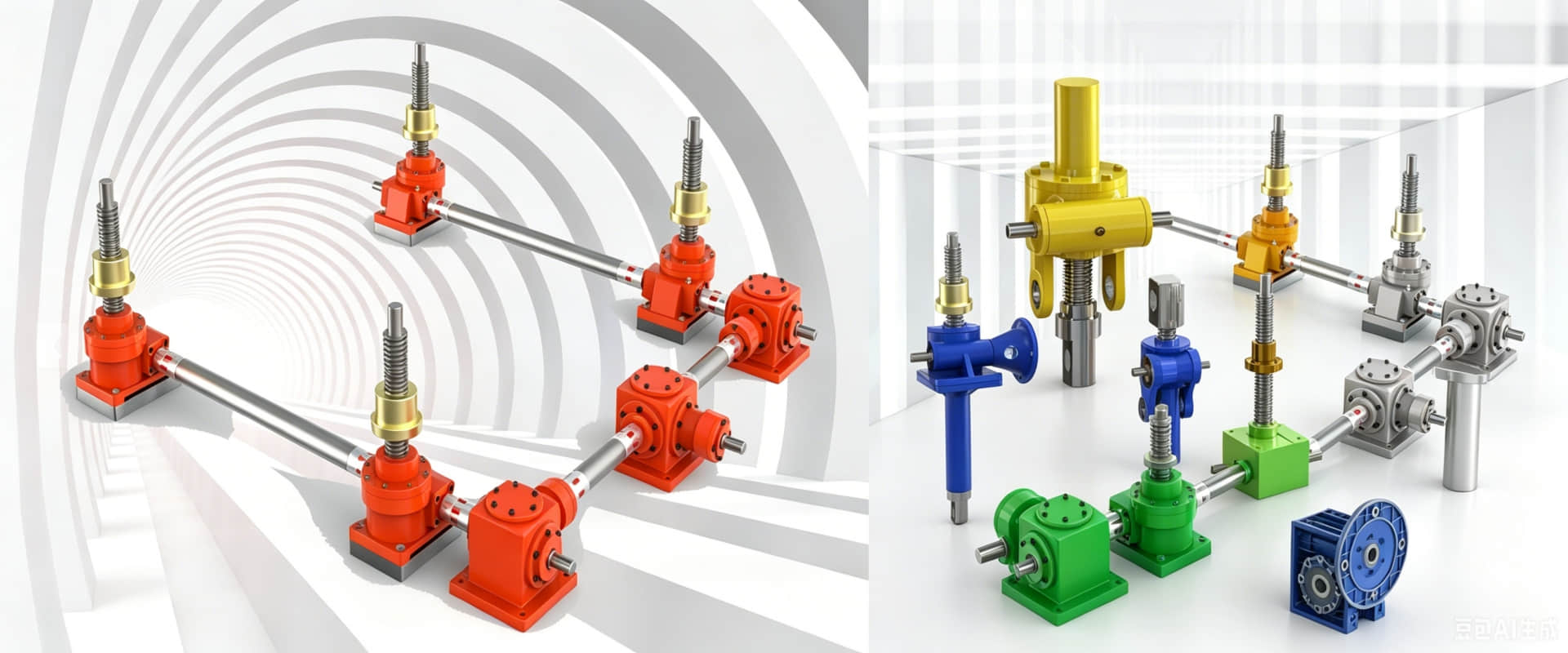
Installation diagram and guide for f series parallel axis helical gearbox
H2: 4 Main Mounting Types + 6 Standard Installation Positions of F Reducer
一、4 Core Structure Mounting Schematic (F/FA/FF/FAF)
F Type – Foot Mounted, Solid Output ShaftFixed via bottom foot base, solid shaft output, widely used for conveyors, horizontal equipment. Simple installation, easy to adjust equipment height.
FA Type – Foot Mounted, Hollow Output ShaftHollow shaft directly sleeves machine main shaft, save coupling parts; match torque arm to offset reaction torque during operation.
FF Type – B5 Flange Mounted, Solid Output ShaftFront flange locking installation, compact layout, ideal for vertical assembly packaging, printing machinery.
FAF Type – B5 Flange Mounted, Hollow Output ShaftFlange + hollow dual advantage, fit tight-space vertical drive; optional shrink disk for non-key connection, high concentricity.
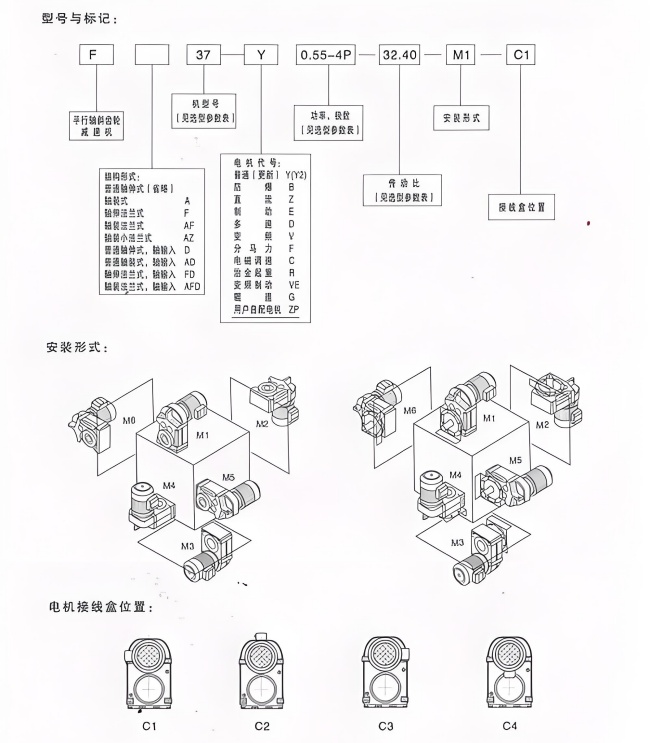
M1: Horizontal motor, gearbox downward (Most universal, best lubrication state, priority recommended)
M2: Motor below, vertical downward output
M3: Horizontal motor, gearbox upside-down (Need custom oil level & breather valve)
M4: Motor above, vertical upward output (Lifting, vertical mixing equipment)
M5/M6: Side tilt mounting, special customized equipment layout
Reminder: Vertical & inverted M3/M4/M5/M6 need to confirm oil filling volume to avoid gear dry grinding and oil leakage.