How to Select a Micro AC Gear Motor – 5-Step Guide for Engineers
H1:How to Select a Micro AC Gear Motor – 5-Step Guide
H2: Step 1 – Determine Output Speed
Calculate required RPM:RPM = (Belt speed × 60) ÷ Roller circumference
H2: Step 2 – Calculate Reduction RatioRatio = Motor RPM ÷ Required Output RPM
Example: 1400 ÷ 50 = 28 → choose 30:1.
H2: Step 3 – Calculate TorqueT (N.m) = 9550 × P (kW) ÷ n (RPM)
Add 1.2–1.5× safety margin for start/stop or shock loads.
H2: Step 4 – Choose Motor Type
Continuous duty → induction
Forward/reverse → reversible
Holding → brake
Variable speed → speed control
H2: Step 5 – Confirm Mounting
Choose flange or foot mount, shaft size, and terminal box position.
Parameters of Micro AC Gear Motor:
| MOTOR FRAME SIZE | 60 mm / 70mm / 80mm / 90mm / 104mm /120MM |
| MOTOR TYPE | Induction Motor / Reversible Motor / Torque Motor / Speed Control Motor |
| OUTPUT POWER | 6W / 15W / 25W / 40W / 60W / 90W / 120 W / 140W / 180W / 200W / 300W/400W(Can Be Customized) |
| OUTPUT SHAFT | 8mm / 10mm / 12mm / 15mm /18mm/22mm Round Shaft, D-Cut Shaft, Key-Way Shaft (Can Be Customized) |
| Voltage type | Single phase 100-240V 50/60Hz; Three phase 200-240V 50/60Hz; Three phase 440-480V 60Hz 4P |
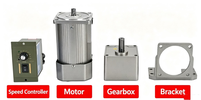
| Accessories | Electric Brake / Fan / Speed Controller / Terminal Box / Thermal Protector |
| GEARBOX FRAME SIZE | 60 mm / 70mm / 80mm / 90mm / 104mm /120mm |
| Gear Ratio | 3K-500K |
📩 Request a Selection Recommendation – Send your speed, torque, voltage, and duty cycle. Our engineers will reply within 24 hours.