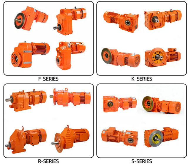
What are the differences between the four series of reducers (R/F/K/S)? How to choose?
In industrial transmission systems, the R, F, K, and S series of hard tooth surface reducers are the most widely used core transmission components, covering the full range of requirements from general conveyor lines to heavy-duty metallurgical equipment. This article will clearly break down the core differences between the four series from dimensions such as transmission structure, performance parameters, and adaptation scenarios, helping you quickly identify the optimal solution for adapting to working conditions.
| Series | transmission mechanism | Output direction | Core Features | Applicable Scenarios |
| R series | Coaxial helical gear | Coaxial (input/output collinear) | Efficiency ≥ 96%, most compact structure | Mixers, conveyor belts, and other space limited scenarios |
| F series | Parallel axis helical gear | Parallel axis offset | Efficiency ≥ 96%, modular design | Packaging machinery and printing equipment |
| Kseries | Helical gear+spiral bevel gear | 90 ° right angle output | The maximum torque is 50kN · m | King of Heavy Duty Mining Machinery, Lifting Equipment, Ball Mill |
| S series | Helical gear+worm gear | 90 ° right angle output | Equipped with self-locking, maximum speed ratio 289:1 | Lifting mechanism, inclined conveyor |
Three step method for selecting four series of hard tooth helical gears:
1.First determine the output direction - choose R for coaxial, K or S for right angle, and F for parallel offset
2.Re determine torque and function - choose K for heavy load, R/F for standard operating conditions,
and S for self-locking
3.Finally, consider space and budget - choose R for space constraints and R/F/S for budget priority