
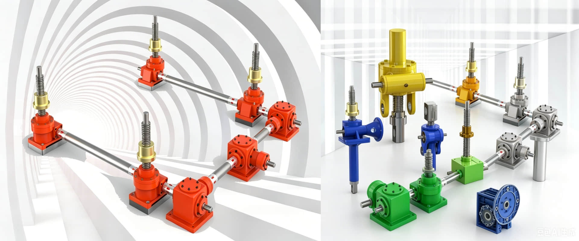
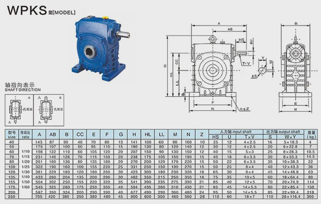
WPKS series cast iron worm gear reducer - dimensions and installation drawings
WPKS Series Worm Gear Reducer – Dimensions & Mounting Drawings
The WPKS series worm gear reducer is an inch-dimension variant of the WP family, featuring a standard input shaft configuration with foot-mounted cast iron housing.
Main features of WP turbine worm reducer
1.Cast iron casing - sturdy and durable, suitable for heavy-duty applications
2.Inch Size Series - Compatible with Imperial Measurement Systems
3.45 # hard steel worm gear+tin bronze worm gear - excellent wear resistance
4.Self locking function - prevents reverse safety
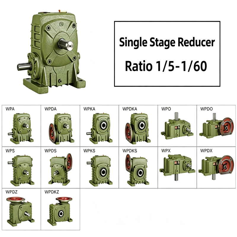
5.Proportion: 10:1-60:1 (single-stage)
Standard Sizes Available
WPKS series covers sizes 50, 60, 70, 80, 100, 120, 135, 155, 175, 200
Mounting Dimensions (Typical Drawing References)
| Dimension | Description | Size 80 (Reference) |
|---|---|---|
| A | Center distance | 80 mm |
| AB | Base mounting hole spacing | 160 mm |
| H | Overall height | 265 mm |
| HL | Overall length | 200 mm |
| Input Shaft | Diameter × Keyway | 22 mm × 7×4 |
| Output Shaft | Diameter × Keyway | 35 mm × 10×38.3 |
Full dimension drawings available – contact us for PDF catalog
Need full dimension drawing, detailed weight table or custom ratio quotation? Fill in your required model, power and installation type via the inquiry form, our transmission engineer will reply within 24 hours with complete specs & weight data.