
AC Motor Speed Controller Forward & Reverse Wiring Diagram
1: AC Motor Speed Controller Forward & Reverse Wiring Diagram
H2: Controller Terminal Layout
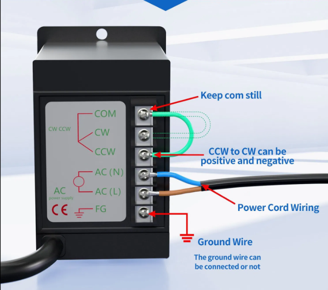
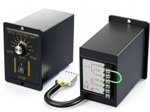
This AC speed controller features six terminals: COM, CW, CCW, AC (N), AC (L), and FG. The COM terminal
must remain fixed and never be moved. The CW and CCW terminals control rotation direction—swapping
them changes the motor from forward to reverse. The AC (N) and AC (L) terminals accept 220V AC power.
The FG terminal is for ground connection and is optional.
H3: Terminal Functions
COM: Common terminal (keep still)
CW: Forward rotation control
CCW: Reverse rotation control
AC (N): Neutral power input
AC (L): Live power input
FG: Ground wire (can be connected or not)
H2: Forward and Reverse Wiring Steps
Connect the power cord to AC (N) and AC (L). For 220V AC, live and neutral are interchangeable.
Keep COM fixed. Connect the control wire to CW for forward rotation.
To reverse rotation, move the control wire from CW to CCW. The direction can be switched by swapping CW and CCW.
Connect the ground wire to FG if required by local electrical codes.
Verify all connections before powering on.
H2: Safety Notes
Disconnect power before wiring.
Do not move the COM terminal.
Ensure the controller matches the motor voltage and power.
Incorrect wiring may damage the motor or controller.
We provide OEM/ODM services for AC speed controllers, including custom wiring harnesses, matched motors, and pre-wired assemblies. Send your technical requirements for a quick quotation.